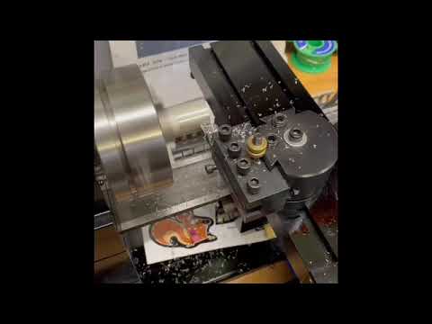
<?xml version="1.0" encoding="UTF-8"?>
<rss version="2.0"
	xmlns:content="http://purl.org/rss/1.0/modules/content/"
	xmlns:wfw="http://wellformedweb.org/CommentAPI/"
	xmlns:dc="http://purl.org/dc/elements/1.1/"
	xmlns:atom="http://www.w3.org/2005/Atom"
	xmlns:sy="http://purl.org/rss/1.0/modules/syndication/"
	xmlns:slash="http://purl.org/rss/1.0/modules/slash/"
	>

<channel>
	<title>www.mikes-models.com blog</title>
	<atom:link href="http://mikes-models.com/blog/index.php/feed/" rel="self" type="application/rss+xml" />
	<link>http://mikes-models.com/blog</link>
	<description>A website for the novice and expert model engineer.</description>
	<lastBuildDate>Thu, 25 Feb 2010 17:52:06 +0000</lastBuildDate>
	<generator>http://wordpress.org/?v=2.9.2</generator>
	<language>en</language>
	<sy:updatePeriod>hourly</sy:updatePeriod>
	<sy:updateFrequency>1</sy:updateFrequency>
			<item>
		<title>Success &#8211; First melt of Aluminium in Home made furnace!</title>
		<link>http://mikes-models.com/blog/index.php/2010/02/success-first-melt-of-aluminium-in-home-made-furnace/</link>
		<comments>http://mikes-models.com/blog/index.php/2010/02/success-first-melt-of-aluminium-in-home-made-furnace/#comments</comments>
		<pubDate>Thu, 25 Feb 2010 17:50:04 +0000</pubDate>
		<dc:creator>Mike Freeman</dc:creator>
				<category><![CDATA[General engineering posts]]></category>
		<category><![CDATA[home foundry and furnace]]></category>
		<category><![CDATA[furnace]]></category>

		<guid isPermaLink="false">http://mikes-models.com/blog/?p=2261</guid>
		<description><![CDATA[First aluminium ingot made during the test burn of my new made gas fired furnace.]]></description>
			<content:encoded><![CDATA[<div id="_mcePaste">Well whilst I was not feeling the best I could I wanted to get out and test the furnace. I had a couple of jobs to do on it first before I could start the fun part.</div>
<div></div>
<div></div>
<div id="_mcePaste">I had done quite a bit a couple of days ago but simply had to give up, but it just left the touch up jobs before I got out the angle grinder and changed the disc to a thin metal cutting one. The first item I want to convert to ingots is the bell housing for my Mk2 Jaguars gearbox rebuild. So three  pieces were cut off for the test.</div>
<div id="_mcePaste">With a little trepidation (in case the lining just fell apart!) I set the burner going and covered the top with some vermiculite panels I use when silver soldering. It would be useful to get an idea on length of time to melt various quantities so a note of the time started and when the melt was seen were recorded. No doubt with experience this will tail off but with my present level of experience all information helps.</div>
<div></div>
<div></div>
<div id="_mcePaste">After 15 minutes the pieces of aluminum had melted and the small crucible was only a third full so I cut off a further piece of the bell housing and added it to the crucible. When that piece had melted I added a small amount of salt and stirred that in. It was really exciting to see the change in the surface of the molten metal as it went very shiny. My understanding is this drives off the hydrogen (source myfordboy) and then added some soda crystals wrapped in aluminum foil) before stirring all in.</div>
<div></div>
<div></div>
<div id="_mcePaste">A quick visit indoors to see SWMBO and creep to get a spoon I could 'borrow' (permanently!) resulted in a quick modification before removing the amount of crud produced and then the crucible was removed before pouring the molten metal into the angle iron ingot moulds welded up some months ago.</div>
<div></div>
<div></div>
<div id="_mcePaste">Lessons learned after this impromptu first melt were :-</div>
<div></div>
<div id="_mcePaste">1.                  Better organisation and a walk through of the whole process before even lighting the burner would have sorted out many inefficiencies!</div>
<div></div>
<div id="_mcePaste">2.                Cut up sufficient material to melt before starting. Better to have to much than cut more whilst you are melting one load.</div>
<div></div>
<div id="_mcePaste">3.                The amount in solid is always less than that seen when molten so fill the crucible up above the top.</div>
<div id="_mcePaste">In general however the session was extremely successful since the furnace suffered no major damage and I had my first melt. Sorted!!!!</div>
<div></div>
<div id="_mcePaste">Now I need to focus on the whole purpose of building the furnace, that of making patterns for my own engines. I also have a few other ideas for items to be made in aluminum so we move on from the building to using stage.</div>
<div></div>
<div>Want to know more (including a video) then go to my main <a href="http://www.mikes-models.com/furnace.html">website.</a> In the meantime here is my wonderful ingot (don't laugh!)</div>
<div>
<div id="attachment_2266" class="wp-caption aligncenter" style="width: 310px"><a href="http://mikes-models.com/blog/wp-content/uploads/2010/02/25-02-2010-furnace-first-032.jpg"><img class="size-medium wp-image-2266" title="25 02 2010 furnace first! 032" src="http://mikes-models.com/blog/wp-content/uploads/2010/02/25-02-2010-furnace-first-032-300x216.jpg" alt="First aluminium ingot made during the test burn of my new made gas fired furnace." width="300" height="216" /></a><p class="wp-caption-text">First aluminium ingot made during the test burn of my new made gas fired furnace.</p></div>
</div>
]]></content:encoded>
			<wfw:commentRss>http://mikes-models.com/blog/index.php/2010/02/success-first-melt-of-aluminium-in-home-made-furnace/feed/</wfw:commentRss>
		<slash:comments>0</slash:comments>
		</item>
		<item>
		<title>Flames in the Furnace! Home made gas fired furnace being built.</title>
		<link>http://mikes-models.com/blog/index.php/2010/02/flames-in-the-furnace-home-made-gas-fired-furnace-being-built/</link>
		<comments>http://mikes-models.com/blog/index.php/2010/02/flames-in-the-furnace-home-made-gas-fired-furnace-being-built/#comments</comments>
		<pubDate>Sat, 20 Feb 2010 18:06:31 +0000</pubDate>
		<dc:creator>Mike Freeman</dc:creator>
				<category><![CDATA[home foundry and furnace]]></category>
		<category><![CDATA[furnace]]></category>

		<guid isPermaLink="false">http://mikes-models.com/blog/?p=2237</guid>
		<description><![CDATA[Furnace is Gas fired home made for melting aluminium is nearly completed and see's a flame for the very first time!]]></description>
			<content:encoded><![CDATA[<p>I pushed on with the furnace project this morning with the aim of designing and producing the method of securing the burner to the furnace body.  I decided to make a clamp out of aluminium and bolt this to two pieces of steel angle iron which in turn would be welded to the furnace frame.</p>
<p>After measuring up I marked out the piece of aluminium and went over to the milling machine.  The first task was to mill out the gap required to let the burners delivery tube. Then the main diameter hole was finished to size by using a milling cutter (after removing as much material as possible using the slot drill). After those two tasks were completed the overall size of the bracket was brought to finished size by milling.</p>
<p>There were 6 holes to drill, 4 for mounting the clamp to the angle iron and 2 tapped 6mm for grub screws which holds the burner head in position (please see photo's) before going to the scrap box to find some angle iron to which the clamp is bolted.</p>
<p>One adjustment had to be made however to get the burner in the right place by means of milling a step on the furnace face side of the clamp. After that its was a quick clean up before starting on the two angle iron brackets. These were brought to shape by measuring against the now nearly finished aluminium bracket. Once they were finished the holes were transferred from the aluminium to the angle iron by steel punches, the first time I used them and was impressed with the results. The set of punches were bought cheaply on eBay and I must say they really made easy work of marking the holes in the correct places.</p>
<p>Once the mounting holes were drilled and tapped into the angle iron the clamp was bolted to them and the bolts trimmed to length by means of the Proxxon and the Dremel cut off discs which performed well. Running out of puff I decided to position the assembly in place and when it all seemed secure thought "why not!" and decided to fire up the burner albeit briefly (I want to bring the temperature up in the furnace gently and for a prolonged period when the lid has cured a little) to see if the burner I am using would work.</p>
<p>After trying to get an old set of matches to work the burner lit and I am confident it will deliver the goods. This may be wishful thinking when its running for a long time but I am still hopeful.</p>
<p>All that remains now is to trim the grub screws that hold the head in place and get the welder out to weld the angle iron brackets in their final resting place and weld the lid hinge in place before making a steel stand to sit the crucible on but it has had a flame in it! Can't wait for the first melt!</p>
<p>Follow its progress on my <a href="http://www.mikes-models.com/furnace.html">main website</a> and here are a few explanation photo's......</p>
<p>--------------------------------------------------------------------------------------------------------------------------------------------------------------------------------------------------------------------------------------------------------------
<a href='http://mikes-models.com/blog/index.php/2010/02/flames-in-the-furnace-home-made-gas-fired-furnace-being-built/100_3810/' title='100_3810'><img width="150" height="150" src="http://mikes-models.com/blog/wp-content/uploads/2010/02/100_3810-150x150.jpg" class="attachment-thumbnail" alt="Marking out the design on the scrap piece of aluminium for the burner clamp to complete the home made gas fired aluminium furnace" title="100_3810" /></a>
<a href='http://mikes-models.com/blog/index.php/2010/02/flames-in-the-furnace-home-made-gas-fired-furnace-being-built/100_3811/' title='100_3811'><img width="150" height="150" src="http://mikes-models.com/blog/wp-content/uploads/2010/02/100_3811-150x150.jpg" class="attachment-thumbnail" alt="Constituent parts for the securing bracket to hold the burner for the gas fired home furnace to melt aluminium." title="100_3811" /></a>
<a href='http://mikes-models.com/blog/index.php/2010/02/flames-in-the-furnace-home-made-gas-fired-furnace-being-built/100_3812/' title='100_3812'><img width="150" height="150" src="http://mikes-models.com/blog/wp-content/uploads/2010/02/100_3812-150x150.jpg" class="attachment-thumbnail" alt="" title="100_3812" /></a>
<a href='http://mikes-models.com/blog/index.php/2010/02/flames-in-the-furnace-home-made-gas-fired-furnace-being-built/100_3813/' title='100_3813'><img width="150" height="150" src="http://mikes-models.com/blog/wp-content/uploads/2010/02/100_3813-150x150.jpg" class="attachment-thumbnail" alt="Trial fitting of the burner to the embryonic clamp" title="100_3813" /></a>
<a href='http://mikes-models.com/blog/index.php/2010/02/flames-in-the-furnace-home-made-gas-fired-furnace-being-built/100_3814/' title='100_3814'><img width="150" height="150" src="http://mikes-models.com/blog/wp-content/uploads/2010/02/100_3814-150x150.jpg" class="attachment-thumbnail" alt="Aluminium clamp  which will be bolted to angle brackets which in turn will be welded to the furnace body" title="100_3814" /></a>
<a href='http://mikes-models.com/blog/index.php/2010/02/flames-in-the-furnace-home-made-gas-fired-furnace-being-built/100_3816/' title='100_3816'><img width="150" height="150" src="http://mikes-models.com/blog/wp-content/uploads/2010/02/100_3816-150x150.jpg" class="attachment-thumbnail" alt="&#039;temp&#039; holding of the brackets for the trial" title="100_3816" /></a>
<a href='http://mikes-models.com/blog/index.php/2010/02/flames-in-the-furnace-home-made-gas-fired-furnace-being-built/100_3817/' title='100_3817'><img width="150" height="150" src="http://mikes-models.com/blog/wp-content/uploads/2010/02/100_3817-150x150.jpg" class="attachment-thumbnail" alt="Not at full belt don&#039;t want to damage the unfired lining yet" title="100_3817" /></a>
</p>
<p><script type="text/javascript">// <![CDATA[
 google_ad_client = "pub-1416942932975097"; /* 468x15, created 30/10/08 */ google_ad_slot = "8577506194"; google_ad_width = 468; google_ad_height = 15;
// ]]&gt;</script></p>
<p><script src="http://pagead2.googlesyndication.com/pagead/show_ads.js" type="text/javascript"></script></p>
]]></content:encoded>
			<wfw:commentRss>http://mikes-models.com/blog/index.php/2010/02/flames-in-the-furnace-home-made-gas-fired-furnace-being-built/feed/</wfw:commentRss>
		<slash:comments>0</slash:comments>
		</item>
		<item>
		<title>Hand Turned wine bottle stopper</title>
		<link>http://mikes-models.com/blog/index.php/2010/02/hand-turned-wine-bottle-stopper/</link>
		<comments>http://mikes-models.com/blog/index.php/2010/02/hand-turned-wine-bottle-stopper/#comments</comments>
		<pubDate>Fri, 19 Feb 2010 17:33:54 +0000</pubDate>
		<dc:creator>Mike Freeman</dc:creator>
				<category><![CDATA[pens and other hand turning]]></category>

		<guid isPermaLink="false">http://mikes-models.com/blog/?p=2231</guid>
		<description><![CDATA[Want to see a hand tuned project? Have a look at my Wine Stopper!]]></description>
			<content:encoded><![CDATA[<p><script type="text/javascript">// <![CDATA[
  google_ad_client = "pub-1416942932975097"; /* 468x15, created 30/10/08 */ google_ad_slot = "8577506194"; google_ad_width = 468; google_ad_height = 15;
// ]]&gt;</script></p>
<p><script src="http://pagead2.googlesyndication.com/pagead/show_ads.js" type="text/javascript"></script></p>
<p>In addition to making pens I have had a go at a wine stopper yesterday. Great for the sealing of opened wine bottles. Have a look at my <a href="http://www.mikes-models.com/pens.html">main website</a> for more information about turning pens,pencils, roller balls and other items. I enjoy it so much I need to find owners or else I can't make any more! So if you want a pen or wine stopper email me and I will give you a choice of pen type and either wood or acrylic for the body. I have some lovely new timbers.....</p>
<p>This is the latest item.....</p>
<div id="attachment_2232" class="wp-caption aligncenter" style="width: 378px"><a href="http://mikes-models.com/blog/wp-content/uploads/2010/02/100_3770.jpg"><img class="size-large wp-image-2232  " title="100_3770" src="http://mikes-models.com/blog/wp-content/uploads/2010/02/100_3770-1024x767.jpg" alt="Wine stopper -makes a lovely present" width="368" height="276" /></a><p class="wp-caption-text">Wine stopper -makes a lovely present. Want one? Then please email me</p></div>
]]></content:encoded>
			<wfw:commentRss>http://mikes-models.com/blog/index.php/2010/02/hand-turned-wine-bottle-stopper/feed/</wfw:commentRss>
		<slash:comments>2</slash:comments>
		</item>
		<item>
		<title>Gas fired furnace -work resumes at last</title>
		<link>http://mikes-models.com/blog/index.php/2010/02/gas-fired-furnace-work-resumes-at-last/</link>
		<comments>http://mikes-models.com/blog/index.php/2010/02/gas-fired-furnace-work-resumes-at-last/#comments</comments>
		<pubDate>Fri, 19 Feb 2010 17:20:20 +0000</pubDate>
		<dc:creator>Mike Freeman</dc:creator>
				<category><![CDATA[General engineering posts]]></category>
		<category><![CDATA[home foundry and furnace]]></category>

		<guid isPermaLink="false">http://mikes-models.com/blog/?p=2220</guid>
		<description><![CDATA[Gas fired aluminium melting furnace for the model engineer continues to be built and is nearing completion with the casting of the lid and manufacture of the hinge mechanism]]></description>
			<content:encoded><![CDATA[<p><script type="text/javascript">// <![CDATA[
 google_ad_client = "pub-1416942932975097"; /* 468x15, created 30/10/08 */ google_ad_slot = "8577506194"; google_ad_width = 468; google_ad_height = 15;
// ]]&gt;</script></p>
<p><script src="http://pagead2.googlesyndication.com/pagead/show_ads.js" type="text/javascript"></script></p>
<div id="_mcePaste">Its been almost three months since I have been able to tackle the re casting of the lid due to my poor method of mixing the lid. I used a trowel and never really got any interchange between the Perlite and the fire cement. It was only after learning that the best methodology is to use your hands like a really big cake mix!</div>
<div id="_mcePaste">I used two pairs of disposable gloves (one on top of the other) when handling the mixture and had the bucket and lid at a comfortable working height. In the end I had just enough materials to cast the lid and also included a plug formed by an old Pot Noodle pot. Just need to have it set off now for a few days.</div>
<div id="_mcePaste">Suitably recharged I thought I should tackle the hinge for the lid. I decided to use a couple of scrap bits of steel from the scrap box. The outer tube is from a handle that was 'saved' from somewhere..... I thought I would mill a slot that would require the lid to be raised, before revolving the lid outward and then dropping into a holding slot slightly higher than the closed postion.</div>
<div id="_mcePaste">The inside bar then had a 6mm metric thread tapped into it so a grub screw could be inserted and act as the pin (see photo's below). The outside tube will be welded to the steel casing of the furnace. The lid part of the tube will be cut later and the bar then welded to the top part.</div>
<div id="_mcePaste">The lid can then be lowered into the base part welded to the main casing and the grub screw then inserted allowing the hinge to operate. We shall see......</div>
<div id="_mcePaste">The remaining tasks are now as follows.</div>
<div id="_mcePaste">1                 Weld the hinge to the lid and base.</div>
<div id="_mcePaste">2                 Make the fitting to attach the burner to the furnace</div>
<div id="_mcePaste">3                 Make a stand for the crucible to stand on inside the furnace.</div>
<div id="_mcePaste">4                 Make up the sand boxes to hold the casting sand.</div>
<div id="_mcePaste">Then fire up the furnace and see what happens! It shouldn't be too long before that happens and certainly within the next fortnight I would hope.</div>

<a href='http://mikes-models.com/blog/index.php/2010/02/gas-fired-furnace-work-resumes-at-last/100_3797/' title='100_3797'><img width="150" height="150" src="http://mikes-models.com/blog/wp-content/uploads/2010/02/100_3797-150x150.jpg" class="attachment-thumbnail" alt="First pour of the mixture for the lid" title="100_3797" /></a>
<a href='http://mikes-models.com/blog/index.php/2010/02/gas-fired-furnace-work-resumes-at-last/100_3799/' title='100_3799'><img width="150" height="150" src="http://mikes-models.com/blog/wp-content/uploads/2010/02/100_3799-150x150.jpg" class="attachment-thumbnail" alt="Now we need to wait for it to set....a few days!" title="100_3799" /></a>
<a href='http://mikes-models.com/blog/index.php/2010/02/gas-fired-furnace-work-resumes-at-last/100_3801/' title='100_3801'><img width="150" height="150" src="http://mikes-models.com/blog/wp-content/uploads/2010/02/100_3801-150x150.jpg" class="attachment-thumbnail" alt="Milling the slot for the hinge" title="100_3801" /></a>
<a href='http://mikes-models.com/blog/index.php/2010/02/gas-fired-furnace-work-resumes-at-last/100_3804/' title='100_3804'><img width="150" height="150" src="http://mikes-models.com/blog/wp-content/uploads/2010/02/100_3804-150x150.jpg" class="attachment-thumbnail" alt="Cleaning up the slot for the pin to traverse" title="100_3804" /></a>
<a href='http://mikes-models.com/blog/index.php/2010/02/gas-fired-furnace-work-resumes-at-last/100_3809/' title='100_3809'><img width="150" height="150" src="http://mikes-models.com/blog/wp-content/uploads/2010/02/100_3809-150x150.jpg" class="attachment-thumbnail" alt="Using a grub screw which will allow assembly" title="100_3809" /></a>

]]></content:encoded>
			<wfw:commentRss>http://mikes-models.com/blog/index.php/2010/02/gas-fired-furnace-work-resumes-at-last/feed/</wfw:commentRss>
		<slash:comments>0</slash:comments>
		</item>
		<item>
		<title>Seal Flywheel and turning mandrel makes some progress.</title>
		<link>http://mikes-models.com/blog/index.php/2010/02/seal-flywheel-and-turning-mandrel-makes-some-progress/</link>
		<comments>http://mikes-models.com/blog/index.php/2010/02/seal-flywheel-and-turning-mandrel-makes-some-progress/#comments</comments>
		<pubDate>Tue, 02 Feb 2010 15:12:37 +0000</pubDate>
		<dc:creator>Mike Freeman</dc:creator>
				<category><![CDATA[General engineering posts]]></category>
		<category><![CDATA[IC model engines]]></category>
		<category><![CDATA[seal engine build]]></category>
		<category><![CDATA[flywheel]]></category>

		<guid isPermaLink="false">http://mikes-models.com/blog/?p=2210</guid>
		<description><![CDATA[Whilst I made an error on this one flywheel for the Seal engine early on I decided to carry on and complete it to verify my methodology. A mandrel was made so the finishing cuts could be made between centres making a non 'wobbling' flywheel!]]></description>
			<content:encoded><![CDATA[<p>I managed to get into the workshop this morning so carried on with the pair of flywheels for the two Seal engines. The need to ensure they do not 'wobble' when running is important so I decided to follow the advice of Edgar T Westbury in his article published during 1947 (!) in the <a href="http://www.model-engineer.co.uk/">Model Engineer magazine</a> and make a mandrel to run between centres.</p>
<p>I decided to turn the mandrel out of  BMS (mild steel) and set the taper by adjusting the top slide over to give the 10 deg inclusive angle. After getting the bar to run true in the 4 jaw chuck, the bar was turned down to just under the 0.25" diameter required to match the end of the crankshafts. The thread I used was 1/4" x 40 tpi (model engineer thread) so I checked the <a href="http://www.mikes-models.com/shopping.html">Drills Taps and Dies reference</a> book in the Home Workshop series (no.12) by Tubail Cain where he recommends a 5% to 10% reduction in size to allow for the Die to cut correctly.</p>
<p>Once the mandrel was made a elongated nut was mad to hold the flywheel against the taper. Once the nut was threaded I drilled out around 1" in length away from the nut. It was then back to the 4 jaw chuck to centre the mandrel, and fit the flywheel.</p>
<p>I was pleased and disappointed at the same time when I ran the lathe because the flywheel ran true! Pleased because of the work done and disappointed because of the work done in turning the mandrel! On reflection I decided that it was still the right thing to have done and really confirmed the trueness of the flywheel.</p>
<p>So that completed all the turning machine jobs and whilst this one is scrap I at least now know the best procedures to produce the flywheel. So the next time I will ready to go full steam ahead and get the two flywheels made.
<a href='http://mikes-models.com/blog/index.php/2010/02/seal-flywheel-and-turning-mandrel-makes-some-progress/100_3644/' title='100_3644'><img width="150" height="150" src="http://mikes-models.com/blog/wp-content/uploads/2010/02/100_3644-150x150.jpg" class="attachment-thumbnail" alt="Mandrel for turning Seal flywheels" title="100_3644" /></a>
<a href='http://mikes-models.com/blog/index.php/2010/02/seal-flywheel-and-turning-mandrel-makes-some-progress/100_3650/' title='100_3650'><img width="150" height="150" src="http://mikes-models.com/blog/wp-content/uploads/2010/02/100_3650-150x150.jpg" class="attachment-thumbnail" alt="Mandrel and &#039;practice&#039; flywheel" title="100_3650" /></a>
<a href='http://mikes-models.com/blog/index.php/2010/02/seal-flywheel-and-turning-mandrel-makes-some-progress/100_3649/' title='100_3649'><img width="150" height="150" src="http://mikes-models.com/blog/wp-content/uploads/2010/02/100_3649-150x150.jpg" class="attachment-thumbnail" alt="ME 1/4&quot; x 40 tpi" title="100_3649" /></a>
<a href='http://mikes-models.com/blog/index.php/2010/02/seal-flywheel-and-turning-mandrel-makes-some-progress/100_3651/' title='100_3651'><img width="150" height="150" src="http://mikes-models.com/blog/wp-content/uploads/2010/02/100_3651-150x150.jpg" class="attachment-thumbnail" alt="Cleaning up the flywheel between centres to stop &#039;wobble&#039;" title="100_3651" /></a>
</p>
<p><script src="http://pagead2.googlesyndication.com/pagead/show_ads.js" type="text/javascript"></script></p>
]]></content:encoded>
			<wfw:commentRss>http://mikes-models.com/blog/index.php/2010/02/seal-flywheel-and-turning-mandrel-makes-some-progress/feed/</wfw:commentRss>
		<slash:comments>0</slash:comments>
		</item>
		<item>
		<title>Warco Band Saw for sale.</title>
		<link>http://mikes-models.com/blog/index.php/2010/01/warco-band-saw-for-sale/</link>
		<comments>http://mikes-models.com/blog/index.php/2010/01/warco-band-saw-for-sale/#comments</comments>
		<pubDate>Sun, 31 Jan 2010 18:18:02 +0000</pubDate>
		<dc:creator>Mike Freeman</dc:creator>
				<category><![CDATA[General engineering posts]]></category>
		<category><![CDATA[Model Engineering items for sale]]></category>
		<category><![CDATA[bandsaw]]></category>

		<guid isPermaLink="false">http://mikes-models.com/blog/?p=2198</guid>
		<description><![CDATA[// 

My purchase of a Clarke bandsaw has meant my Warco bandsaw has to go. It has been a great servant to me and is still working fine. If it wasn't for the fact I wanted a vertical cutting ability I should not have replaced it.
Included in the sale are a couple of new blades [...]]]></description>
			<content:encoded><![CDATA[<p><script type="text/javascript">// <![CDATA[
 google_ad_client = "pub-1416942932975097"; /* 468x15, created 30/10/08 */ google_ad_slot = "8577506194"; google_ad_width = 468; google_ad_height = 15;
// ]]&gt;</script></p>
<p><script src="http://pagead2.googlesyndication.com/pagead/show_ads.js" type="text/javascript"></script></p>
<p>My purchase of a Clarke bandsaw has meant my Warco bandsaw has to go. It has been a great servant to me and is still working fine. If it wasn't for the fact I wanted a vertical cutting ability I should not have replaced it.</p>
<p>Included in the sale are a couple of new blades so its all ready to go. If you are interested then please email me. It will need to be picked up from Brixham in Devon. Below are some photo's of the bandsaw. I have fixed the price realistically at £50 so first come, first served.</p>

<a href='http://mikes-models.com/blog/index.php/2010/01/warco-band-saw-for-sale/100_3640/' title='100_3640'><img width="150" height="150" src="http://mikes-models.com/blog/wp-content/uploads/2010/01/100_3640-150x150.jpg" class="attachment-thumbnail" alt="" title="100_3640" /></a>
<a href='http://mikes-models.com/blog/index.php/2010/01/warco-band-saw-for-sale/100_3642/' title='100_3642'><img width="150" height="150" src="http://mikes-models.com/blog/wp-content/uploads/2010/01/100_3642-150x150.jpg" class="attachment-thumbnail" alt="" title="100_3642" /></a>
<a href='http://mikes-models.com/blog/index.php/2010/01/warco-band-saw-for-sale/100_3643/' title='100_3643'><img width="150" height="150" src="http://mikes-models.com/blog/wp-content/uploads/2010/01/100_3643-150x150.jpg" class="attachment-thumbnail" alt="" title="100_3643" /></a>

]]></content:encoded>
			<wfw:commentRss>http://mikes-models.com/blog/index.php/2010/01/warco-band-saw-for-sale/feed/</wfw:commentRss>
		<slash:comments>0</slash:comments>
		</item>
		<item>
		<title>One step forward then two back with the Seal Flywheels!</title>
		<link>http://mikes-models.com/blog/index.php/2010/01/one-step-forward-then-two-back-with-the-seal-flywheels/</link>
		<comments>http://mikes-models.com/blog/index.php/2010/01/one-step-forward-then-two-back-with-the-seal-flywheels/#comments</comments>
		<pubDate>Sun, 31 Jan 2010 18:04:51 +0000</pubDate>
		<dc:creator>Mike Freeman</dc:creator>
				<category><![CDATA[General engineering posts]]></category>
		<category><![CDATA[IC model engines]]></category>
		<category><![CDATA[seal engine build]]></category>

		<guid isPermaLink="false">http://mikes-models.com/blog/?p=2184</guid>
		<description><![CDATA[A silly misread of the plans leads to the scrapping (when finished) of the first flywheel for the pair of Seal engines.]]></description>
			<content:encoded><![CDATA[<p><script type="text/javascript">// <![CDATA[
 google_ad_client = "pub-1416942932975097"; /* 468x15, created 30/10/08 */ google_ad_slot = "8577506194"; google_ad_width = 468; google_ad_height = 15;
// ]]&gt;</script></p>
<p><script src="http://pagead2.googlesyndication.com/pagead/show_ads.js" type="text/javascript"></script></p>
<p>I managed to get out into the workshop a couple of days ago and carried on with the manufacture of the two brass flywheels I am making for the pair of Seal engines. My session started well enough until I misread the dimensions and removed too much metal from the face! I decided however to carry on with making the flywheel so I could iron out any other problems and also make the tool for the flywheel starting cord. The pictures below show the progress and tool profile.</p>
<p>It is a big advantage to grind your own tools and the profile soon ground. I used the plan to get the correct profile. I took the cuts very carefully and got to depth but the next time I shall use the parting tool to remove more material and then turn to the profiled HSS tool. This should make the process even easier.</p>
<p>I will now have to prepare another blank. Fortunately I still have enough material but will have to be careful.</p>

<a href='http://mikes-models.com/blog/index.php/2010/01/one-step-forward-then-two-back-with-the-seal-flywheels/100_3628/' title='100_3628'><img width="150" height="150" src="http://mikes-models.com/blog/wp-content/uploads/2010/01/100_3628-150x150.jpg" class="attachment-thumbnail" alt="Too much taken off - read the wrong label on the plan!" title="100_3628" /></a>
<a href='http://mikes-models.com/blog/index.php/2010/01/one-step-forward-then-two-back-with-the-seal-flywheels/100_3629/' title='100_3629'><img width="150" height="150" src="http://mikes-models.com/blog/wp-content/uploads/2010/01/100_3629-150x150.jpg" class="attachment-thumbnail" alt="Decided to carry on until completed. Learn more that way." title="100_3629" /></a>
<a href='http://mikes-models.com/blog/index.php/2010/01/one-step-forward-then-two-back-with-the-seal-flywheels/100_3631/' title='100_3631'><img width="150" height="150" src="http://mikes-models.com/blog/wp-content/uploads/2010/01/100_3631-150x150.jpg" class="attachment-thumbnail" alt="Using the plan to check the profile for the tool tip." title="100_3631" /></a>
<a href='http://mikes-models.com/blog/index.php/2010/01/one-step-forward-then-two-back-with-the-seal-flywheels/100_3632/' title='100_3632'><img width="150" height="150" src="http://mikes-models.com/blog/wp-content/uploads/2010/01/100_3632-150x150.jpg" class="attachment-thumbnail" alt="Flywheel starting cord profile cut to depth" title="100_3632" /></a>

]]></content:encoded>
			<wfw:commentRss>http://mikes-models.com/blog/index.php/2010/01/one-step-forward-then-two-back-with-the-seal-flywheels/feed/</wfw:commentRss>
		<slash:comments>0</slash:comments>
		</item>
		<item>
		<title>Update on the Clarke Bandsaw</title>
		<link>http://mikes-models.com/blog/index.php/2010/01/update-on-the-clarke-bandsaw/</link>
		<comments>http://mikes-models.com/blog/index.php/2010/01/update-on-the-clarke-bandsaw/#comments</comments>
		<pubDate>Mon, 25 Jan 2010 19:57:16 +0000</pubDate>
		<dc:creator>Mike Freeman</dc:creator>
				<category><![CDATA[General engineering posts]]></category>
		<category><![CDATA[Tool Reviews]]></category>
		<category><![CDATA[bandsaw]]></category>

		<guid isPermaLink="false">http://mikes-models.com/blog/?p=2177</guid>
		<description><![CDATA[During the last cut of the last brass bar I was cutting for the first use of the bandsaw the blade broke at the weld! I was fortunate enough to have bought a bi-metal blade on eBay so I could carry on.
Phoning Machine Mart proved to be a less stressful experience that I expected. After being [...]]]></description>
			<content:encoded><![CDATA[<p>During the last cut of the last brass bar I was cutting for the first use of the bandsaw the blade broke at the weld! I was fortunate enough to have bought a bi-metal blade on eBay so I could carry on.</p>
<p>Phoning <a href="http://www.machinemart.co.uk/shop/product/details/cbs45md-41-2in-x-6in-metal-cutting-ban">Machine Mart</a> proved to be a less stressful experience that I expected. After being put through to 'some one in technical' I spoke to to their engineer who explained that whilst it was the blade, they needed to see if the machine caused it or whether it was a faulty blade.</p>
<p>My description was quickly accepted and the engineer said they would replace the blade even though it was classed as a 'consumable'. So that was good news. I went onto say I was pleased with the saw but the stand was rubbish! He said that a friend of his had bought the same model and held the same views as myself, he built a new stand for it. That convinced me that I should go the same route so as soon as some good weather comes, I will take my Mk Jaguar out of its comfy home and fabricate a stand in the resultant space.</p>
<p>20 minutes after finishing my call to Machine Mart I had a return call where I was told that the man responsible for retail blades would not open a pack of five for just one blade so they decided to send me a pack instead! Common sense but its nice I didn't have to fight for them. So well done Machine Mart and that's a gold star.........until the next time.......well done</p>
]]></content:encoded>
			<wfw:commentRss>http://mikes-models.com/blog/index.php/2010/01/update-on-the-clarke-bandsaw/feed/</wfw:commentRss>
		<slash:comments>0</slash:comments>
		</item>
		<item>
		<title>Review of the Dremel Speedclic system</title>
		<link>http://mikes-models.com/blog/index.php/2010/01/review-of-the-dremel-speedclic-system/</link>
		<comments>http://mikes-models.com/blog/index.php/2010/01/review-of-the-dremel-speedclic-system/#comments</comments>
		<pubDate>Mon, 25 Jan 2010 19:45:29 +0000</pubDate>
		<dc:creator>Mike Freeman</dc:creator>
				<category><![CDATA[Tool Reviews]]></category>
		<category><![CDATA[tool review]]></category>

		<guid isPermaLink="false">http://mikes-models.com/blog/?p=2169</guid>
		<description><![CDATA[ 
 
 
Its early days yet since I have just received the Dremel Speedclic cut off system today. However initial observations are favourable. It is an 'expensive' system on the face of it so I will need to see its overall durability, the efficiency of the cutting disc as well as how long they [...]]]></description>
			<content:encoded><![CDATA[<p><em> </em></p>
<p><em> </em></p>
<p><em> </em></p>
<div id="_mcePaste"><span style="font-style: normal;">Its early days yet since I have just received the Dremel Speedclic cut off system today. However initial observations are favourable. It is an 'expensive' system on the face of it so I will need to see its overall durability, the efficiency of the cutting disc as well as how long they will last before coming up with a final rating.</span></div>
<div><span style="font-style: normal;"><br />
</span></div>
<div id="_mcePaste"><span style="font-style: normal;">I purchased my set with a pack of spare discs from Axminster tools and on inspection the quality of materials is very good, but no less than you should expect for its price. The true cost of Dremels cut off disc system will depend upon both the durability of the click mandrel as well as the life of the cutter so some time will need to pass.</span></div>
<div><span style="font-style: normal;"><br />
</span></div>
<div id="_mcePaste"><span style="font-style: normal;">On opening the package the mandrel seems strong enough and of course I tried to fit one disc without reading the brief illustrated instruction sheet that accompanied the package. It soon became obvious that you don't put the disc on and press it down whilst turning in one direction so I am ashamed to say I had a look at the destruction's. You simply pull down on the top mandrel collar and place the disc inside before giving it a twist (making sure the Dremel painted side is facing away from the mandrel and tool), then release the collar and your done.</span></div>
<div><span style="font-style: normal;"><br />
</span></div>
<div id="_mcePaste"><span style="font-style: normal;">I always run any new disc up to speed for a short time, no matter what its size. More than likely this is not needed but its something drummed into me at an earlier age. When trying the disc on a 3mm bolt it proved both quick and accurate. I like the large size of the disc but on some small work it may prove to big. My answer will be to run one or two disc down to a small size then replace with new and keeping these smaller diameters for other occasions.</span></div>
<div><span style="font-style: normal;"><br />
</span></div>
<div id="_mcePaste"><span style="font-style: normal;">One major advantage obvious even this early on is the changing methodology. No more loosing very small screws!</span></div>
<div><span style="font-style: normal;"><br />
</span></div>
<div id="_mcePaste"><span style="font-style: normal;">On the face of it the expense is worth it, but I reserve judgement until I know how long the disc will last.</span></div>
<p><span style="font-style: normal;">Its early days yet since I have just received the Dremel Speedclic cut off system today. However initial observations are favourable. It is an 'expensive' system on the face of it so I will need to see its overall durability, the efficiency of the cutting disc as well as how long they will last before coming up with a final rating.</span></p>
<p><span style="font-style: normal;"><br />
I purchased my set with a pack of spare discs from Axminster tools and on inspection the quality of materials is very good, but no less than you should expect for its price. The true cost of Dremels cut off disc system will depend upon both the durability of the click mandrel as well as the life of the cutter so some time will need to pass.</span></p>
<p><span style="font-style: normal;"><br />
On opening the package the mandrel seems strong enough and of course I tried to fit one disc without reading the brief illustrated instruction sheet that accompanied the package. It soon became obvious that you don't put the disc on and press it down whilst turning in one direction so I am ashamed to say I had a look at the destruction's. You simply pull down on the top mandrel collar and place the disc inside before giving it a twist (making sure the Dremel painted side is facing away from the mandrel and tool), then release the collar and your done.</span></p>
<p><span style="font-style: normal;"><br />
I always run any new disc up to speed for a short time, no matter what its size. More than likely this is not needed but its something drummed into me at an earlier age. When trying the disc on a 3mm bolt it proved both quick and accurate. I like the large size of the disc but on some small work it may prove to big. My answer will be to run one or two disc down to a small size then replace with new and keeping these smaller diameters for other occasions.</span></p>
<p><span style="font-style: normal;"><br />
One major advantage obvious even this early on is the changing methodology. No more loosing very small screws!</span></p>
<p><span style="font-style: normal;"><br />
On the face of it the expense is worth it, but I reserve judgement until I know how long the disc will last.</span></p>
<p><span style="font-style: normal;"> </span></p>
<div id="attachment_2173" class="wp-caption aligncenter" style="width: 310px"><a href="http://mikes-models.com/blog/wp-content/uploads/2010/01/100_3623.jpg"><img class="size-medium wp-image-2173" title="100_3623" src="http://mikes-models.com/blog/wp-content/uploads/2010/01/100_3623-300x225.jpg" alt="" width="300" height="225" /></a><p class="wp-caption-text">Dremel Instructions and Speedclic</p></div>
]]></content:encoded>
			<wfw:commentRss>http://mikes-models.com/blog/index.php/2010/01/review-of-the-dremel-speedclic-system/feed/</wfw:commentRss>
		<slash:comments>0</slash:comments>
		</item>
		<item>
		<title>Flywheel turning hits a problem &#8211; 4 jaws to big!</title>
		<link>http://mikes-models.com/blog/index.php/2010/01/flywheel-turning-hits-a-problem-4-jaws-to-big/</link>
		<comments>http://mikes-models.com/blog/index.php/2010/01/flywheel-turning-hits-a-problem-4-jaws-to-big/#comments</comments>
		<pubDate>Sun, 17 Jan 2010 16:41:37 +0000</pubDate>
		<dc:creator>Mike Freeman</dc:creator>
				<category><![CDATA[General engineering posts]]></category>
		<category><![CDATA[IC model engines]]></category>
		<category><![CDATA[seal engine build]]></category>
		<category><![CDATA[flywheel]]></category>
		<category><![CDATA[Westbury Seal 15cc engine]]></category>

		<guid isPermaLink="false">http://mikes-models.com/blog/?p=2158</guid>
		<description><![CDATA[Flywheel for Seal 15cc 4 cylinder petrol engine hits a snag when the jaws of the 4 jaw chuck prove to large to fit inside the rear cavity. Another approach is needed to complete the flywheel]]></description>
			<content:encoded><![CDATA[<p><script type="text/javascript">// <![CDATA[
  google_ad_client = "pub-1416942932975097"; /* 468x15, created 30/10/08 */ google_ad_slot = "8577506194"; google_ad_width = 468; google_ad_height = 15;
// ]]&gt;</script></p>
<p><script src="http://pagead2.googlesyndication.com/pagead/show_ads.js" type="text/javascript"></script></p>
<p>Just had  a short session this morning and continued with the flywheel project for the Seal engines being built. However after getting the outside turning round and facing off I was left with 2.6315" diameter (need 2.5" finished size) so was pleased with progress. I don't know what specification the brass is made to but it machines great!</p>
<p>So feeling smug I thought I would rough turn the inside of the cavity (will be the rear of the finished flywheel) and using one of my home made boring bars before reversing the blank and bringing the front to roughly the correct diameter so that finishing cuts could be made all the better when running the lathe at faster speeds than the unbalanced blank would allow. This is when I hit a snag! One that I did not expect or had come across before using the Turner lathe.</p>
<p>The diameter of the cavity when finished, will be 1.75" and when I reversed the jaws, they were too big to go inside the cavity! So my smart thoughts went out the window! I will now have to remove the remaining excess by another method.</p>
<p>I did however resolve a question I had about the small diameter of the valve liners for the Seal. The answer came to me when studying the drawings last night and the reason is the need for the valve spring to sit over the outside of the valve guide. Mystery solved and I will just have to be careful when making them!</p>
<p>When I resume work on the flywheel I will hold the turned part in the 4 jaws as normal. A few photo's below show progress........</p>

<a href='http://mikes-models.com/blog/index.php/2010/01/flywheel-turning-hits-a-problem-4-jaws-to-big/100_3612/' title='100_3612'><img width="150" height="150" src="http://mikes-models.com/blog/wp-content/uploads/2010/01/100_3612-150x150.jpg" class="attachment-thumbnail" alt="Thank goodness there is more than the 2.5&quot; diameter required" title="100_3612" /></a>
<a href='http://mikes-models.com/blog/index.php/2010/01/flywheel-turning-hits-a-problem-4-jaws-to-big/100_3614/' title='100_3614'><img width="150" height="150" src="http://mikes-models.com/blog/wp-content/uploads/2010/01/100_3614-150x150.jpg" class="attachment-thumbnail" alt="Boring the cavity which will be the rear of the finished flywheel" title="100_3614" /></a>
<a href='http://mikes-models.com/blog/index.php/2010/01/flywheel-turning-hits-a-problem-4-jaws-to-big/100_3615/' title='100_3615'><img width="150" height="150" src="http://mikes-models.com/blog/wp-content/uploads/2010/01/100_3615-150x150.jpg" class="attachment-thumbnail" alt="My 4 jaw chuck proved to big for the cavity in the flywheel!" title="100_3615" /></a>

]]></content:encoded>
			<wfw:commentRss>http://mikes-models.com/blog/index.php/2010/01/flywheel-turning-hits-a-problem-4-jaws-to-big/feed/</wfw:commentRss>
		<slash:comments>3</slash:comments>
		</item>
	</channel>
</rss>
